Tsuga Search
Measurement Protocols
Will Blozan and Jess Riddle, September 2006

All mensuration techniques
within the Tsuga Search will adhere to the following protocols. They are based
on tested methods and have proven to be accurate and repeatable.
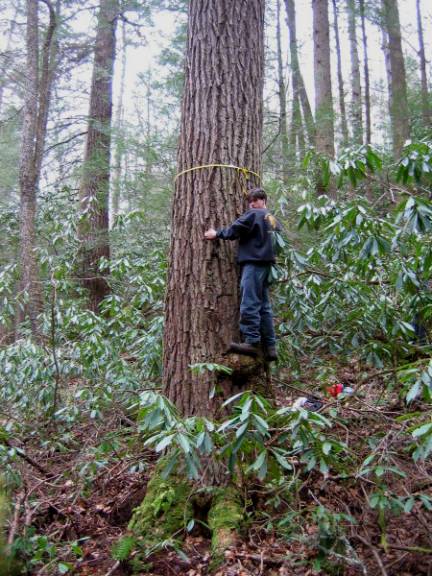
Diameter measurements
Tree diameter is obtained by
measuring the girth of the stem at 4.5 feet (1.37 m- “breast height, BH”) above
average ground (midslope) and dividing by pi.
Girth is always measured perpendicular to the long
axis of the stem.
Trees having multiple
stems at BH but single pith at ground level (as determined by a visual “pith
trace”, see below) are measured as individuals with the narrowest point
recorded as the diameter. Fused trees
forking below breast height but with independent piths will be measured as individuals
at 4.5 feet.
![]()
Tree height measurements
Tree heights are measured
with a laser rangefinder and clinometer. The rangefinder provides the distance
to the tree top and the clinometer provides the corresponding angle with
respect to eye level. The sine of the angle times the distance gives the
elevation difference between the measurer’s eye and the tree top. The same procedure is repeated with the base of the tree
in place of the tree top. Adding the two elevation differences gives the total
vertical height of the tree. Using the rangefinder to measure the distance to
multiple tops may help identify the highest point, especially when the true
high point appears lower on the horizon than other tops. All tree heights
are vertical distance, not trunk length.

Total tree height= H1+H2,
where H1= SIN (A1)*D1 and H2= SIN (A2)*D2
Tree volume measurements
Volume measurements can be
achieved via ground-based or aerial methods. Ground–based measurements are
obtained by the use of a reticled monocular, laser rangefinder, and a
clinometer. Aerial measurements are direct tape measures obtained by a climber
in the tree.
Ground-based
A reticled
monocular can be used to accurately measure diameters from great distances. The
distance from the measured section of trunk multiplied by the reticle reading
and divided by an optical factor results in the diameter of the target. Lasered
distances are estimated to the nearest 1/10th whole unit by finding
“click-over” to the next unit relative to the rear of the monocular. This
device coupled with a clinometer for heights and section lengths allows for a
volume determination to be made without climbing the tree (see below).
.

As illustrated in the above
diagram, the scale is oriented by fine adjustments of the tripod to line up
with and perpendicular to the edge of the trunk at the “0” point on the scale.
The optical intercept of the opposite side is read against the scale and
estimated to the nearest 1/100th unit. The section of tree above
would be recorded as intercepting 1.41 on the reticle scale. To calculate the
diameter the following formula would be used:
Diameter= (Reticle scale) X (distance
to target) ÷ (optical factor*)
If the section above were 90
feet (27.4 m) away the diameter would be:
Diameter= (1.41) X (90) ÷ 75; which is 1.69
feet (0.52 m)
(*Note: the
optical factor is supplied by the manufacturer, and
specific to the monocular model.)
Trees with limited
visibility of the trunk that obscure laser bounces are measured by using
a single baseline measurement to the base of the tree and a single laser shot
distance to the highest portion of the trunk that is clearly visible. This
allows us to still measure a portion of the trunk visible to the monocular but
not directly measurable by the laser. After a point is located with a good view of the entire tree a
tripod is set up with the monocular attached. The baseline distance to the center (side) of the base of the tree is
measured and the distance to the center
(side) of the highest visible point of the trunk is measured with the
rangefinder.

This procedure
creates a triangle encompassing the measurable portion of the trunk, with
vertices at the observer’s eye and the bottom and top of the measurable section
of trunk. The position of and distances to measured points along the trunk can
then be interpolated based on the clinometer angle.
If the tree
deviates significantly (+/- 2 feet; .6 m) from a straight bole the distance to
the midpoint of the trunk must be measured for every sighting. Widths of the
measured sections are then calculated and the height of the measurement points
and lengths of the resulting sections are calculated by the angles obtained
from the clinometer.
Tree climbs
Accurate aerial trunk
measurements can be obtained by a tree climber. All points of measurement are
referenced for height above ground to a fixed tape in the tree which is initiated
at the highest point and terminated at midslope. If the top of the tree is not safely reachable a pole or stick is used to place the
end of the tape at the highest point. Measurement intervals are subjectively
chosen based on changes in trunk taper. An area where a change in profile is
observed (in or out) is measured with a diameter tape perpendicular to the
lean. Clear sections of trunk are selected so as to not include branch collars,
burls, etc. Typically, around fifteen measurements are taken on single-trunked
trees in addition to those obtained for the base (see below). Generally,
measurements are no more than ten feet (3 m) apart. Trunk reiterations are
measured and added to the final trunk volume. Reiterations are identified by an
upturned branch that has gained apical dominance and formed a new vertical trunk.
A bifurcation is a split in the trunk that forms two or more similarly sized
ascending trunks. Bifurcations often form a fused section that cannot be accurately
measured with a tape. Small bifurcation lengths are terminated at
estimated pith origination. Reiteration lengths are terminated at the point of
trunk contact.
Significantly large [>2.5
feet (75 cm) diameter] fused sections are measured with
a frame mapping technique (see photo below). With two
climbers, each on opposite sides of the tree, an area of fusion is selected to
be measured. Two, six foot (~2 m) poles are connected
by a thin rope threaded through opposite ends so they are adjustable (we used
non-stretch arborist throw line and garden stakes). The poles are temporarily
tensioned and the distance between the ends 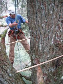 measured. Adjustments are made until they are
parallel and perpendicular to the axis of the trunk. The slight tension between
the poles holds them steady against the trunk. The climbers sight across the
poles and agree on a “0” point from which to begin measurements. The “0” point
is the “point of contact” at one end of the frame when a retracting steel
carpenter’s tape is stretched across at 90 degrees to the poles. The “0” point
is marked on both sides as the common reference. This reference is the “0” on
the X axis for each pole, and the tape is used to measure in to the trunk
across the entire intercept with the pole. Thus, the trunk profile can be
plotted as the distance from the X axis reference point and the distance in to the trunk
as the Y axis. Points where the tree contacts the pole is recorded as whatever
the X distance is and a “0” for the Y. We measured at changes in the trunk
profile and to the nearest 1/8th inch (.32 cm). Graphing of the data illustrates
the cross-sectional representation of the fused trunk. See example below.
measured. Adjustments are made until they are
parallel and perpendicular to the axis of the trunk. The slight tension between
the poles holds them steady against the trunk. The climbers sight across the
poles and agree on a “0” point from which to begin measurements. The “0” point
is the “point of contact” at one end of the frame when a retracting steel
carpenter’s tape is stretched across at 90 degrees to the poles. The “0” point
is marked on both sides as the common reference. This reference is the “0” on
the X axis for each pole, and the tape is used to measure in to the trunk
across the entire intercept with the pole. Thus, the trunk profile can be
plotted as the distance from the X axis reference point and the distance in to the trunk
as the Y axis. Points where the tree contacts the pole is recorded as whatever
the X distance is and a “0” for the Y. We measured at changes in the trunk
profile and to the nearest 1/8th inch (.32 cm). Graphing of the data illustrates
the cross-sectional representation of the fused trunk. See example below.
The data are then entered into a trapezoidal area function in an
Excel™ spreadsheet
and converted into area so as to calculate the equivalent circular area to use
in the volume formula.
Volume calculations
Cumulative trunk volume is
calculated by adding the measured sections of the tree together. No limb volume
is measured or estimated. The formula for the frustum of a cone is used for all
trunk sections.
Volume= H*π/3*(r12+r22+r1*r2)
Where H is the height of the frustum and r1 and r2
are the radii of the top and bottom of the frustum. The
aerial or ground-based measurements are added to a basal section that is
measured in more detail than those above due to a typically less columnar trunk
profile. For the purpose of the Tsuga Search, the wedge of wood below high side
ground formed by a tree growing on a slope is dealt with in the following way:
The midslope point is carefully established by using clinometers to transpose
the highest side of the ground contact (below duff) against the lowest side.
The elevation positioned in-between these is considered the base of the tree and
is used in both the basal volume calculations and the absolute height
determination. The lowest measurable point (LMP) above root flare is taken as
the lowest measurement, even if several feet above the midslope point. The LMP
is then extended down to midslope as a column.

This technique, though
crude, should satisfactorily approximate the volume of the flared and fissured section
(fissures are not illustrated above). In cases where the trunk is extremely
incised we may choose a section higher up the trunk (and thus smaller) to
represent the basal column. Detailed footprint maps would be very time
consuming and not result in significant gains in accuracy relative to the rest
of the tree.
Relative canopy height
The heights of canopy trees
surrounding the target tree will be measured as described above. One additional
set of measurements will be taken to ascertain the surrounding canopy height
relative to the target tree. This is achieved by measuring the relative elevation difference between the tree and
the target tree. A rangefinder and clinometer is used to obtain the vertical
offset, and the distance between the trees is obtained during the canopy tree
mapping described below.
Canopy tree mapping
All trees over four inches
(10cm) diameter whose trunk center is within 82 feet (25 m) of the center of
the subject tree will be mapped. Distance is obtained with a laser rangefinder
and recorded to the nearest whole meter. Measurements are taken from the basal midpoint
of each tree and no slope correction is used. Species, diameter and live/dead
are recorded. A compass is used to obtain the azimuth from the target tree to
the mapped tree and recorded to the nearest whole degree. The compass is set to
“0” degrees declination. The result is then graphed as seen in the example
below.